
The detected key is displayed at (“KEY= 5”) second line column 9 on wards. The LCD displays the “KEYPAD LCD TEST” as welcome screen at the first line Number of seconds since start “SEC= 123” is displayed at the second line column one. The Arduino LiquidCrystal and Keypad library is used for displaying the status and detecting key press. The Column pins are connected to 6,7,8 and 9th digital IO pins of Arduino. The Row pins are connected to 5,4,3 and 2nd digital IO pins of Arduino. Repeat until a key press (are multiple) is identified. Scan (Read) the Row One to Row Four, to find the key. The key is decoded through Column selection / Row read. In a simple technique, the 16 keys of matrix keypad is connected with 8 digital IOpins of Arduino.

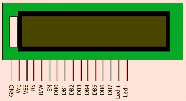
Matrix key pad is arranged by push button switches in rows and columns. If the display is not visible, adjust the Contrast pot (1K), to make it visible. The 16x2 LCD display is connected to the Arduino (A0,A1,A2,A3,A4,A5) analog IO pins, where those pins are configured as digital in / out, where LCD operates at 4 bit data mode. It consists of back light and contrast adjustment function and each dot matrix has 5×8 dot resolution. The LCD is available in a 16 pin package. The 16x2 is very common type LCD, with two rows, and each row displays 16 characters of either 5x7 or 5x8 dot matrix characters. Parts and components Īrduino Uno board 16x2 LCD 1 K ohm potentiometer 4x4 matrix keypad This intractable is about interfacing 16×2 LCD and 4x4 matrix keypad with Arduino microcontroller. Similarly character LCD display is used for indicating the system status / parameters. Arduino Interfacing with LCD Display and Keypad In Embedded system design, matrix keypad (4x4, 4x3, 3x3 or 5x5) is used for key in the user inputs.


 0 kommentar(er)
